Division 02 • Engineering & Design

Turn incomplete inputs into clear engineering output.

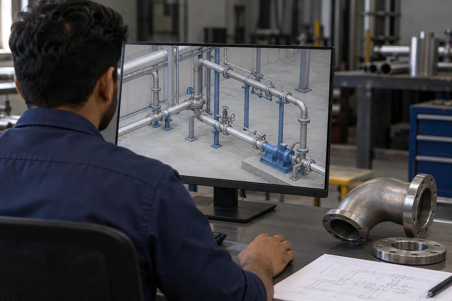
Mechanical engineering and design support covering 3D modelling, 2D drafting, piping design and layout, production drawings, machine/component design, BOMs, DFM/DFA, reverse engineering and technical documentation.

CADParts & assemblies
2DProduction drawings
DFMManufacturing review
REReverse engineering
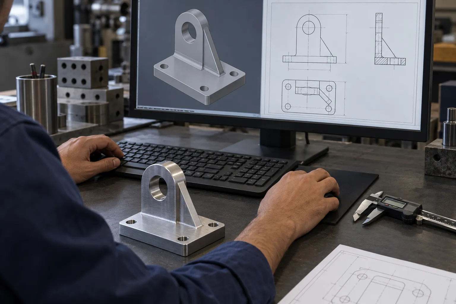
Engineer reviewing a bracket model and manufacturing drawing at a CAD workstation
What we deliver · Services · Focused routes

Clear engineering definition before manufacturing, sourcing or modification begins.

We turn sketches, samples, photographs, old drawings and incomplete requirements into technical outputs another person can manufacture, inspect, assemble or review.

What we deliver

Concrete outputs from this division

013D CAD modelsParts and assemblies with practical manufacturing intent.
02Production drawingsControlled 2D drawings for machining, fabrication or inspection.
03Assembly & fabrication drawingsInterfaces, mounting, weldments and build information.
04BOM & technical packsStructured component lists and supporting design documentation.
05Reverse-engineered dataMeasured geometry and replacement-part definition from existing items.
06Design review outputsDFM/DFA observations, revisions and technical clarification.
Services we provide

Scope that can be combined around the requirement

Mechanical product design3D CAD modelling2D draftingReverse engineeringProduction drawing preparationBOM preparationDFM / DFA reviewDrawing revision & conversionJig / fixture design supportProduct-development assistance

Start with the drawing, part, machine, document or outcome you already have. We will help define the correct route and the missing information.

Discuss this requirement →
Engineering that moves the job forward

A CAD file is useful only when the next person can act on it.

Good engineering design reduces ambiguity before production, sourcing, inspection or assembly begins. We structure the available evidence, identify the missing information and convert it into a practical technical output.

The starting point can be a sketch, sample, worn component, PDF drawing, dimension sheet, photograph or an existing model that needs correction.

Design intentGeometry, dimensions and manufacturing logic brought together.
Core engineering capability

From concept definition to production-ready documentation.

Scope is built around the job in front of you rather than a fixed service package.

01

3D Mechanical CAD

Component and assembly models built around functional geometry, fit and manufacturability.

Parts • Assemblies • Concepts
02

2D Production Drawings

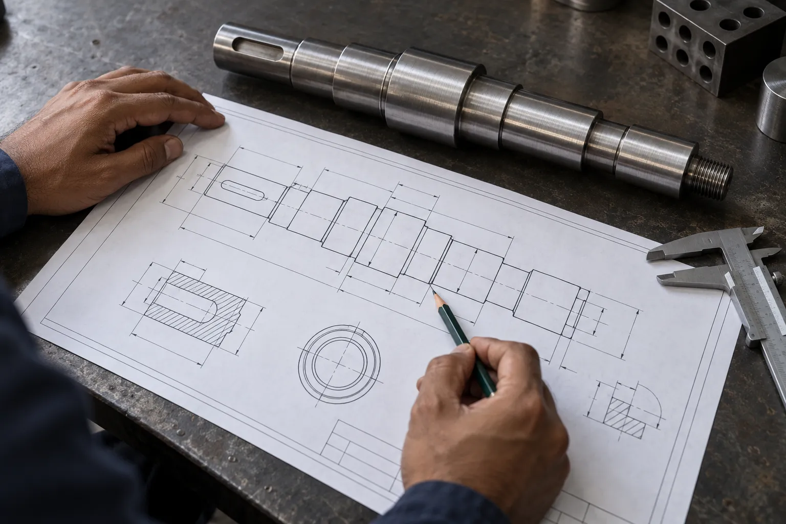
Views, dimensions, notes and drawing structure prepared for manufacturing and inspection use.

Dimensions • Notes • Release
03

Reverse Engineering

Rebuild usable geometry and documentation from samples, measurements or legacy components.

Sample • Measure • Recreate
04

DFM / DFA Review

Review geometry for manufacturing method, assembly sequence, access, tolerances and avoidable complexity.

Manufacture • Assemble • Simplify
05

BOM & Assembly Support

Structured part references, assembly relationships and technical documentation for clearer execution.

BOM • Structure • Traceability
06

Drawing Revision Support

Update legacy drawings, incorporate approved changes and improve technical clarity before release.

Revise • Check • Control
What the work can look like

Visual engineering output, not abstract consultancy.

Different inputs need different levels of modelling, drafting, validation and release control.

A controlled engineering route

From evidence to an actionable technical deliverable.

The workflow is intentionally simple: confirm what exists, identify what is missing, develop the engineering output, then check it before release.

Start with your current input →
01

Capture the requirement

Review sample, drawing, dimensions, photographs, mating parts and expected function.

02

Resolve missing information

Confirm interfaces, material, tolerances, manufacturing limits and required output format.

03

Develop & review

Create the model or drawing and check the design against the agreed technical intent.

04

Release the usable output

Provide the agreed CAD, drawing, BOM, revision or engineering recommendation clearly.

Useful starting inputs

You do not need a perfect brief.

  • Existing drawing, PDF, sketch or old CAD
  • Physical sample or component photographs
  • Critical dimensions and mating-part information
  • Material, load, environment or application constraints
  • Manufacturing process or supplier limitations
  • Required output format and revision expectation
Typical deliverables

Clear engineering outputs.

  • 3D part, assembly and layout models
  • 2D production, fabrication and inspection drawings
  • Piping layouts and related design drawings
  • Machine / fixture / component design documentation
  • BOM, MTO and assembly documentation where applicable
  • Reverse-engineered geometry, DFM/DFA observations and controlled revisions
Start from the evidence you already have

Have a part, sample, drawing or concept that needs engineering clarity?

Send the available material. We will identify the missing inputs and the most practical route to a usable engineering deliverable.