
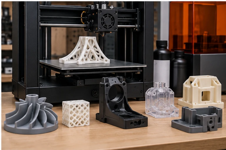
Do not apply one universal tolerance to every 3D-printed feature. Accuracy depends on process, machine, material, orientation, feature size, support strategy and post-processing.
CAD dimension is not automatically finished-part dimension
Additive manufacturing builds material layer by layer. Thermal effects, resin cure, support removal, warpage and stair-stepping mean that geometry and orientation influence the achievable tolerance.
FDM
FDM is excellent for prototypes, jigs and many functional parts, but features can vary with layer orientation and thermal shrinkage. Protolabs publishes industrial FDM dimensional accuracy around ±0.3% with a lower limit around ±0.3 mm for its process; other printers and materials can differ considerably.
SLA/resin
SLA can achieve finer features and smoother surfaces. Protolabs publishes much tighter capabilities for its SLA systems, but still notes that geometry and orientation affect tolerance.
Designing mating parts
- Add intentional clearance rather than modeling two parts at exactly the same nominal size.
- Identify critical dimensions on the drawing.
- Expect holes to print undersize on some FDM systems.
- Consider drilling/reaming critical holes after printing.
- Use metal inserts where repeated threaded assembly is required.
First article is valuable
For repeat production, print one set first, measure it, test fit/function and then lock the orientation, material, slicer parameters and any compensation before continuing the batch.
This article is general guidance for preliminary engineering and shop-floor understanding. The drawing, applicable standard, machine/tooling OEM instructions, process-specific safety requirements and qualified engineering judgment take priority.