
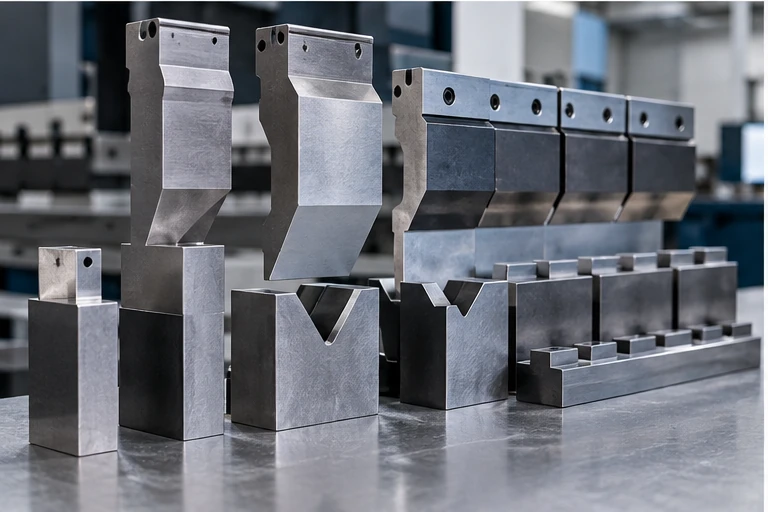
For air bending mild steel, a V-die opening near 8× material thickness is a common starting point—not a universal rule. Material, tooling, radius, flange length and tonnage must still be checked.
What actually happens during bending?
The outer surface of the sheet stretches while the inner surface compresses. Between them is a neutral axis whose length changes far less. Bend allowance calculations estimate the arc length of that neutral axis so a correct flat pattern can be developed.
V-die opening
For many air-bending applications, a V opening around eight times the material thickness is a familiar starting point. Bystronic notes this “rule of 8” as a common selection method, but also points out that real parts often require exceptions. The selected die affects inside radius, minimum flange, tonnage and angular performance.
Inside bend radius
In air bending, the sheet forms a radius according to material behaviour and the die opening rather than simply copying the punch radius. Bystronic gives about 16% of V-opening as a useful mild-steel reference, but stainless, aluminium, high-strength steels and different processes behave differently.
Bend allowance and K-factor
A common engineering expression is:
The correct K-factor is process-dependent. Production tooling, material and bend method should drive the flat pattern, not an assumed universal K-factor.
Before bending, confirm
- Material grade and thickness.
- Grain direction where relevant.
- Inside radius and final angle.
- Flange lengths and hole positions.
- Tooling availability and tonnage.
- Whether dimensions are specified inside, outside or across bends.
Springback
After unloading, elastic recovery opens the angle slightly. The amount depends strongly on material, strength, thickness, radius and process. Compensate with the machine/tooling method rather than applying a generic correction to every material.
This article is general guidance for preliminary engineering and shop-floor understanding. The drawing, applicable standard, machine/tooling OEM instructions, process-specific safety requirements and qualified engineering judgment take priority.